Skip to content

Direct Liquid Cooling It dissipates heat directly from selected server components via cooling plates and a coolant. This can facilitate the cooling of high-performance processors and accelerators, especially in high-density rack environments. The heat must then be dissipated via the building’s HVAC system or repurposed; air cooling is often still necessary for other components. Whether this technology is economically and environmentally viable depends on the hardware, load profile, heat dissipation, and operating conditions at the specific location.
Understanding Direct Liquid Cooling
In Direct Liquid Cooling (DLC), a liquid directly absorbs heat from selected server components. In the widely used direct-to-chip configuration, a Cooling Plate for example, on a CPU or an accelerator. The coolant flows through channels in the plate, heats up, and dissipates the energy via connected pipes.

In a single-phase system, the refrigerant remains in a liquid state during normal operation. Two-phase processes, on the other hand, utilize a phase change in the cooling medium; their design and operational requirements cannot be easily derived from a single-phase cycle. Immersion cooling is also a different concept: in this method, components are immersed in a suitable cooling medium rather than simply being connected to it via cooling plates.
Cooling dissipates heat; it does not prevent it from being generated. A CPU still requires electrical energy to perform its computational tasks, most of which is dissipated as heat. DLC can influence the energy requirements of cooling technology; however, the installation of cooling plates does not result in lower IT power consumption or automatically lead to savings for the entire data center.
Direct-to-Chip becomes particularly interesting at high Rack density: When many high-performance processors are operating in a confined space, a large amount of heat must be dissipated from a small area. The fluid absorbs some of this heat directly from the components instead of first releasing it entirely into the ambient air. Whether the retrofit is worthwhile also depends on the building’s cooling system, load profile, and operating conditions.
The article on [... ] provides an overview of other approaches and their areas of application. Liquid Cooling of Servers in the Data Center. When designing a specific DLC system, it is also crucial to determine how the fluid circuit will be connected to the building's heat dissipation system.
The Path of Heat
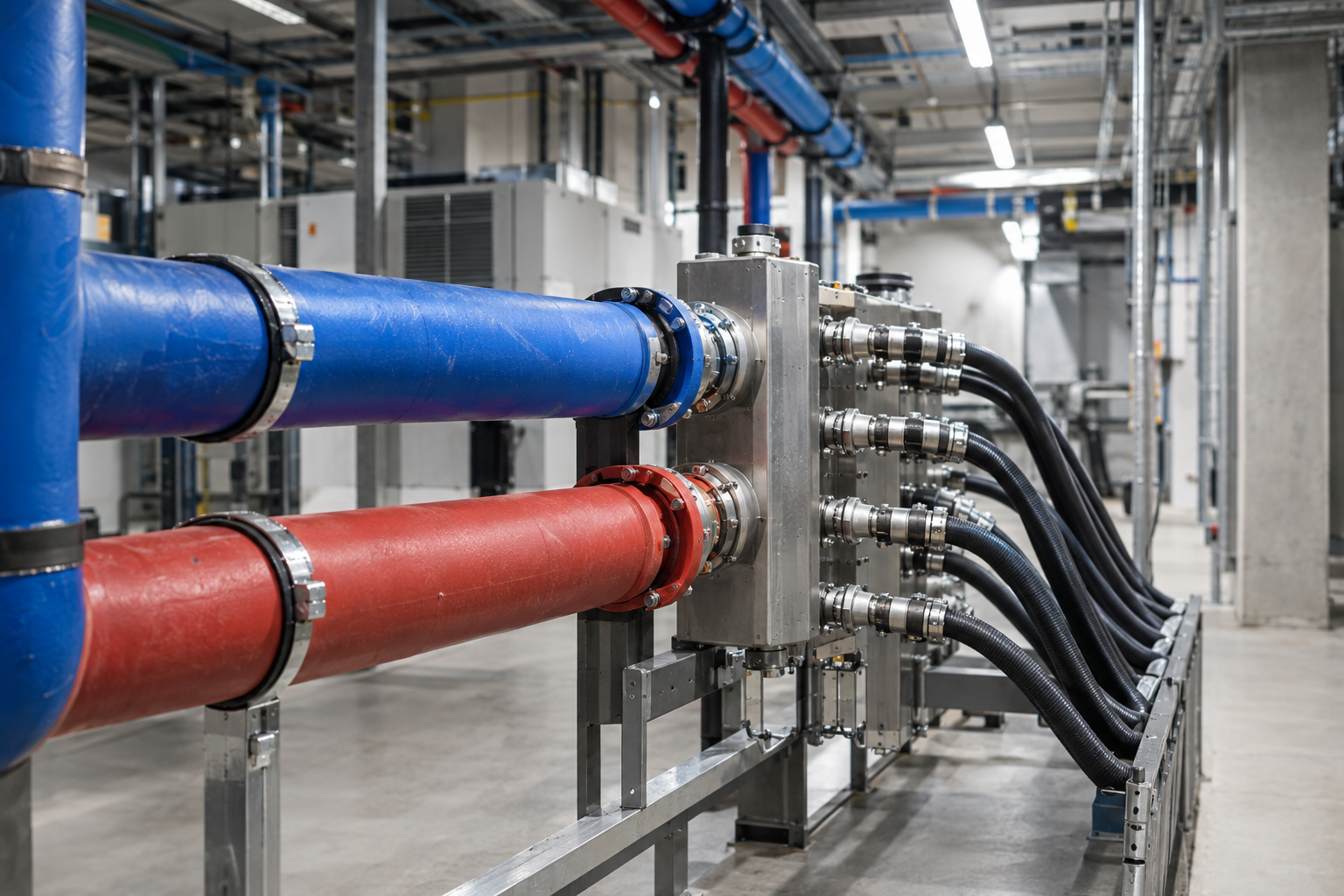
The heat path begins at the contact surface between the component and the cold plate. The heated fluid flows through hoses and fittings to a manifold, which connects multiple servers or cooling paths to the circuit. From there, it typically flows to a Cooling Distribution Unit (CDU), which supplies and regulates the IT-side circuit.
In a liquid-to-liquid CDU, a Heat Exchanger the energy from the IT loop to a building-side loop. The two media do not need to mix in the process. Pumps, sensors, and controls support the intended flow rate and temperature control; depending on the architecture, a CDU can be mounted in a rack or serve multiple racks.
The process doesn’t end at the heat exchanger: The building must continue to dissipate the absorbed heat. Depending on the system and operating conditions, options for this include recoolers, cooling towers, or chillers. The appropriate combination depends, among other things, on the required temperatures, the outdoor climate, and operating conditions throughout the year.
An alternative to simply releasing heat into the environment is to utilize it through a suitable consumer. For this to work, supply and demand must align in terms of timing; temperature levels and distance are also relevant factors. If the available temperature is insufficient, a heat pump may be necessary. The mere presence of a fluid line does not in itself indicate actual heat utilization.
Many liquid-cooled servers remain Hybrid Systems. Cooling plates do not necessarily cover all components; the remaining components continue to dissipate heat into the air. NVIDIA describes such air-cooled residual components for GB200 configurations. Therefore, the airflow path and available air cooling must be sufficient for the remaining load even when a large portion of the heat is dissipated via liquid cooling.
Classifying Temperatures and Interfaces Correctly
When connecting a server, simply specifying „liquid-cooled“ is not sufficient. Designers need the operating data approved for the specific configuration and must verify that it is compatible with the CDU, distribution system, and building infrastructure. A suitable connection can only be established when all components involved are compatible under the intended load and operating conditions.
The Supply Temperature refers to the temperature of the medium as it flows toward the device to be cooled. It must fall within the device’s specified operating range; at the same time, it influences the conditions under which the building’s cooling system can dissipate heat. A higher temperature may be advantageous for certain cooling designs, but must not exceed the permissible limit for the specific server.
The required flow rate describes how much refrigerant must flow through the cooling path in a given period of time. The Pressure loss occurs, among other places, at cooling plates, hoses, and connections. The pump and piping design must ensure the required flow rate while accounting for these resistances and, at the same time, comply with the components’ permissible pressure limits.
Equally important are coolant quality and material compatibility. Manufacturer requirements may pertain, for example, to the composition of the medium and the handling of contaminants. Approved hoses, couplings, and seals must be compatible with the medium and the respective connection; a mechanically compatible part is not automatically approved for the intended operation.
ASHRAE defines W-classes for building-side water supply systems. While such a class helps classify the supply, it does not replace equipment approval and does not automatically define the conditions in the separate IT circuit. Values provided by a manufacturer or for one side of the circuit should therefore not be applied to other devices, connections, or media without verification.
A Comparison of Four Cooling Methods
When choosing a cooling system, it's not just a matter of whether a liquid is used. What matters is, where the heat is absorbed and what infrastructure is required for this in the server and in the building. The four approaches also differ in terms of whether air continues to flow through the IT equipment.
| Procedure | Heat absorption | IT Adjustment and Residual Air | Key Planning Question |
|---|---|---|---|
| Air cooling | Air absorbs heat from the server and carries it away. | No fluid connections for compatible servers; air cooling handles the IT heat load. | Is the airflow and cooling capacity sufficient for the rack load? |
| Rear-Door Heat Exchanger | A liquid-cooled heat exchanger on the rack door absorbs heat from the exhaust air. | Servers are generally air-cooled; airflow within the rack remains necessary. | How are the door, fluid supply, and access to the rack integrated? |
| Direct-to-Chip | Fluid absorbs heat from cooling plates on selected components. | Compatible cooling plates and connectors are required; other components may require air cooling. | Are the servers, distribution systems, and building cooling systems coordinated with one another? |
| Immersion | IT components transfer heat to a suitable dielectric liquid medium. | Appropriate hardware and a customized maintenance plan are required; submerged components do not require air cooling. | Are the hardware allocations, containers, and service processes appropriate? |
For moderate and spatially distributed loads, existing air cooling may be sufficient, provided that the airflow and temperature reserves are appropriate for actual operation. A rear-door heat exchanger, on the other hand, attaches to the rack without fundamentally changing the server’s heat dissipation to cooling plates. Nevertheless, the fluid supply and access to the rear of the rack must still be planned.
In environments with high thermal density, direct-to-chip cooling can facilitate heat dissipation directly from processors and accelerators. Immersion shifts heat absorption to a liquid bath, but has a greater impact on integration and maintenance. Which solution makes sense for a given location therefore depends not only on rack density but also on compatible hardware, the cost of retrofitting, and available heat dissipation capacity.
Planning High-Density Racks in the Inventory
A concrete example of high rack density is NVIDIA's GB200 NVL72: The manufacturer specifies a required cooling capacity of 120 kW per rack for this rack design. This value describes the requirements of the configuration in question, not a general performance limit for Direct Liquid Cooling and no commitment regarding other systems.
Even with this system, cooling is not limited to liquid: NVIDIA documents air-cooled components. When planning the installation site, therefore, both the liquid supply and the remaining airflow requirements of the specific system being delivered must be taken into account. The project-specific connection specifications are binding; a flat-rate value taken from the example is not.
For existing facilities, planning begins with the actual and expected load distribution: Which racks will remain air-cooled, which will be equipped with cooling plates, and where are they located? From this, it is possible to Cooling Zones and determine the respective requirements for air and liquid cooling. A single high rack load should not be confused with a uniform load throughout the entire data center.
Next, check the cable routing, space for the distribution unit and CDU, and accessibility for maintenance. The existing building cooling system must be capable of dissipating the additional heat even under the intended operating conditions. The fact that a CDU can be installed in the room does not, in and of itself, say anything about the available recooling capacity.
To finish off, a well-coordinated redundancy concept: Operators must determine which loads should continue to be supplied in the event of a cooling path failure and how maintenance affects the remaining capacity. Only with these requirements and the manufacturer’s data can retrofits, expansions, and operations be reliably sized.
Heat Balance and Potential Uses
The heat output describes how quickly heat is transferred. The heat energy transferred over a period of time is calculated as power multiplied by time, assuming the power remains constant. This distinction is important when sizing a cooling system or evaluating the potential heat transfer over a period of time.
An illustrative calculation example: Assuming that a constant 40 kW of heat is dissipated over the course of one hour, multiplying 40 kW by one hour yields 40 kWh of transported thermal energy. This is not a measurement. The result does not imply either an electricity savings or that the entire amount of heat is available or usable by a consumer.
For a real Waste heat utilization The temperature must be appropriate for the customer's needs. If it is too low, a heat pump can raise the temperature; the electricity required for this is then included in the overall balance. Higher fluid temperatures can make integration easier, but they do not replace the need to evaluate the specific system.

When planning, operators should compare the available heat supply with a potential customer’s demand over time. They should also determine whether a storage solution is feasible for the specific project. A theoretical annual heat output alone does not guarantee year-round utilization.
When making an investment decision, operators should also evaluate the connection to the customer and the cost of additional equipment on a site-by-site basis. The heat transported cannot simply be considered in its entirety as recovered output. A reliable assessment requires specific data on the planned use.
Ensure Safe Operation and Maintenance
A maintainable liquid cooling system requires more than just accessible servers. For each connection, it should be clear which Quick-Connect Couplings The manufacturer specifies where the affected section can be shut off and how to safely disconnect a device from the system. These steps are part of a site-specific service procedure that also includes restarting the system and checking the connections.
Before replacing any equipment, responsibilities and the impact on the other racks must be clarified. A shared distribution can result in a shutdown affecting more than one server. Therefore, wiring diagrams, labeled connections, and the equipment manufacturer’s specifications should be available on-site; any required replacement parts must be compatible with the installed model.
Coolant quality is also the responsibility of the operator. The materials, fluid, and treatment must be compatible so that corrosion or deposits, for example, do not impair functionality. The applicable tests, threshold values, and replacement intervals are determined by the requirements of the components and the specific cooling system, not by a blanket recommendation regarding water.
To Leak Detection These include appropriately placed sensors, reliable alarm transmission, and a documented response. The team must know who receives the alarm, assesses the affected area, and takes action in accordance with site procedures. An automatic shutdown may be specified for a particular project, but it is neither available in every system nor the only possible response.
Maintenance and troubleshooting procedures should be coordinated: If a sensor is covered during service work or an alarm is temporarily suppressed, procedures for restoring them must also be in place. Records of interventions and anomalies help identify recurring problems and prepare for upcoming maintenance windows in a targeted manner.
Systematically Narrow Down Malfunctions
If the temperature of a component rises, the heat sink isn't necessarily the cause. First, check the IT load and compare the temperature curve with the published limits for the specific hardware. An increase in load can affect heat dissipation; the key factor is whether the system is still operating within its specifications under the intended operating conditions.
You can then check the cooling path step by step: Is the flow temperature at the designated measurement point within the permissible range? Does the flow rate meet the value required for the unit? Both values must match the configuration actually in use. An acceptable value at the building supply alone does not confirm that the server is also being supplied correctly.
A modified Pressure loss may indicate a change in the flow path, but does not explain the cause without further investigation. Compare the available pressure and flow data with the specifications and the previous operating conditions. Next, inspect the CDU, its alarms, and the heat transfer to the building side; any interventions must be performed by trained personnel in accordance with the manufacturer’s and site procedures.
In a hybrid system, residual air cooling is also part of the diagnostic process. If air paths are blocked or the intended air supply is not functioning as planned, components that are not liquid-cooled may be affected. Therefore, a liquid cooling circuit that appears to be functioning normally does not rule out a thermal problem within the same rack.
A leak alarm is handled separately from temperature diagnostics in accordance with the local emergency response plan. If a cooling path fails, the documented failure response plan determines which load is transferred or which system is shut down in a controlled manner. Alarm and escalation procedures should function even if the cause has not yet been determined; improvised work on pressurized lines is not a substitute for proper diagnostics.
Evaluating Cost-Effectiveness and Green Hosting
For an environmental comparison, the PUE The ratio of the total annual energy consumed in the data center to the annual IT energy consumption. The WUE compares the annual water consumption at the site to the annual IT energy consumption. These two values can only be meaningfully compared if the time period and measurement boundaries are disclosed.
A low PUE value does not automatically mean low absolute emissions or low water consumption. For Green Hosting Therefore, other factors—such as total energy demand, the emissions profile or electricity mix, and absolute water usage—are also relevant. A growing IT load can increase a facility’s energy consumption, even if the ratio of total energy to IT energy improves.
Even a closed-loop IT system does not necessarily make the entire operation water-free: another stage of heat dissipation can cause water to evaporate. When it comes to waste heat, it is not just the theoretical supply that matters, but the heat actually used. For this to work, the temperature and the user's time requirements must be compatible; a heat pump may require additional energy.
Cost-effectiveness depends on the location. Compare the expected load profile and planned rack density with the investment costs for compatible IT equipment, power distribution, CDU, and building modifications. Add to this maintenance, energy, water (if applicable), and the costs of redundancy and failover provisions. Compare these items over the same operating period with an alternative that is realistically designed for the location.
For hosting customers, it makes sense to ask providers about the measurement period, location data, and the actual extent of waste heat utilization, rather than drawing conclusions about environmental impact based solely on cooling technology. The article discusses further developments in infrastructure and sustainability in the Hosting Trends for 2026 in.
Sources and Current State of Knowledge
Status of the research:
Research and source status: November 4, 2026. No chart is provided, as no comparable, reliable operational data is available. S10, Revision 2, could not be fully reviewed for content due to a retrieval error; the relevant statements were narrowed down and substantiated based on the available Revision 1 (S7).
https://www.opencompute.org/projects/cooling-environments/cold-plate/
https://ashrae.org/technical-resources/topics-and-initiatives/ai-data-center/energy-and-thermal-efficiency
https://docs.nvidia.com/multi-node-nvlink-systems/multi-node-tuning-guide/system.html
https://www.opencompute.org/documents/ocp-acs-liquid-cooling-cold-plate-requirements-pdf
https://handbook.ashrae.org/Handbooks/A15/IP/A15_CH19/a15_ch19_ip.aspx
https://developer.nvidia.com/blog/nvidia-contributes-nvidia-gb200-nvl72-designs-to-open-compute-project/
https://www.energy.gov/cmei/femp/cooling-water-efficiency-opportunities-federal-data-centers